This is a compact high-voltage converter designed for direct control by a microcontroller. It does not include a digital shutdown feature — instead, the MCU simply sets the high-voltage output level.
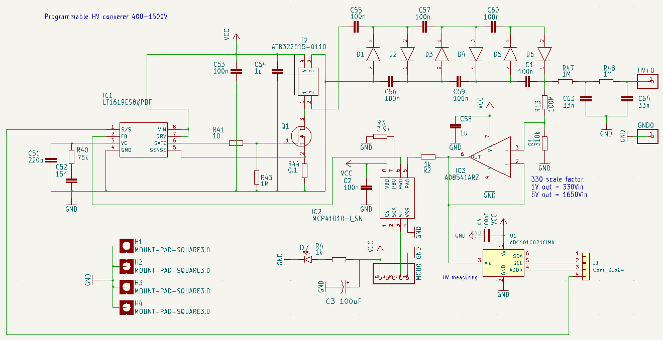
The converter uses a basic flyback topology built around the LT1619 PWM controller. For the high-voltage transformer, I selected the ATB322525-0110, which is a 1:10 photoflash-type transformer. A high-performance MOSFET, driven by the LT1619, switches the primary winding to generate high-voltage pulses on the secondary side.
These pulses are then fed into a three-stage voltage multiplier, providing an overall multiplication factor of approximately six. The feedback loop that regulates the output voltage is implemented using a 100 MΩ / 310 kΩ divider connected to the multiplier output, before the HV RC-RC filter (1 MΩ and 33 nF). The divided-down voltage is buffered by an AD8541 operational amplifier to provide enough drive capability for the next stage: a programmable voltage divider based on the MCP41010.
The MCP41010 is a digitally controlled potentiometer with 255 taps and a total resistance of 10 kΩ (linear). The MCU selects the desired tap position via SPI, accurately defining the output voltage.
The latest revision of the board also integrates a high-voltage monitor: the ADC101C021, which can be read via a dedicated I²C interface. Revision 1 of the board only provides an SPI port and requires a +3.3 V / +5 V supply. Revision 2 adds the I²C connection for the onboard ADC, while maintaining the same supply requirements.
Example Arduino code for controlling the MCP41010 can be downloaded here: HV module arduino example