Finally I’ve made it! Yes, I’ve built an X-Ray machine for non destructive inspection of circuits and objects.
The level of radiation generated by this device is sufficent to induce cancer or radiation illness, please don’t build and don’t operate such device. There is also another risk: it requires very high voltage to be operated. It generates very high and potentially lethal voltages.
How it’s made this demostrative prototype of X-Ray machine?
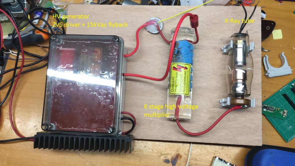
Look at my device. From the left to the right you can see:
- HV generator, ZVS type, drives a TV type flyback transformer. It’s not used in flyback mode because ZVS outputs a pure sinewave so it’s just working as standard high frequency transformer. It’s output it’s around 15kV with 16V drive voltage. The ZVS diver starting voltage is 7V so, changing the voltage into the range 7-32V I can select output voltage. The whole assembly is enclosed into an electrical juncton box and insulated with silicon gel.
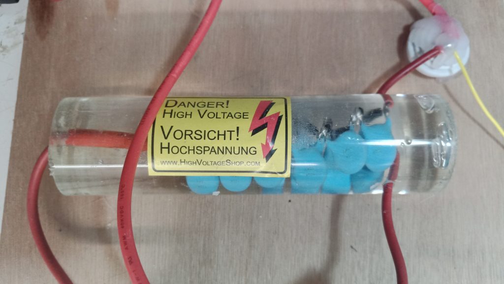
- SHV 6 stage voltage multiplier. This part it’s made with a 6 stage voltage multiplier enclosed in epoxy. It takes the 15kV input and multiply it x6 to the output. It’s maximum output voltage with 16V input to the ZVS is 90kV. I’ve operated it to 120kV maximum without any troubles for diodes and It’s scarry!
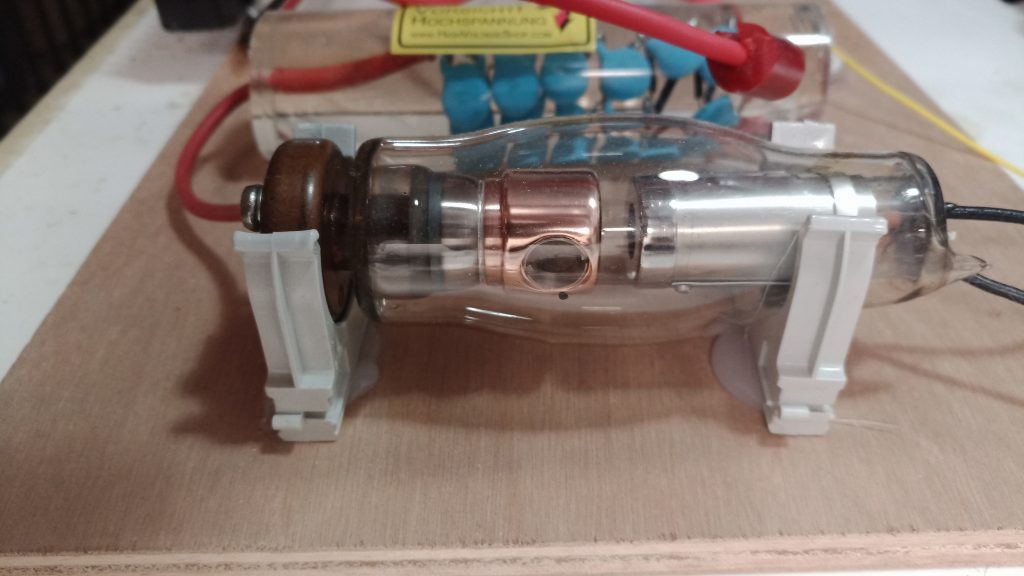
- X-Ray tube. This unit is a generic replacement for medical use. It’s a surplus tube from Ukraine and was made during soviet era. The big copper disk on the bottom is the anode. The two black wires on the top are the filament wires. You have to connect one of the two leads to the multiplier GND in order to provide a return path to the catode for the electrons that will circulate into the tube during operation.
How to generate X-Rays?
Basicly you just need to properly feed an X-ray generator tube. What it needs to be happy and hot? A proper high voltage for the anode and enought current flowing into it’s filament to heat the catode.
The heated catode generates a cloud of electrons around it that are accellerated to the anode by HV. When they reach the anode, the hit force is enought to convert some of them into X-Rays.
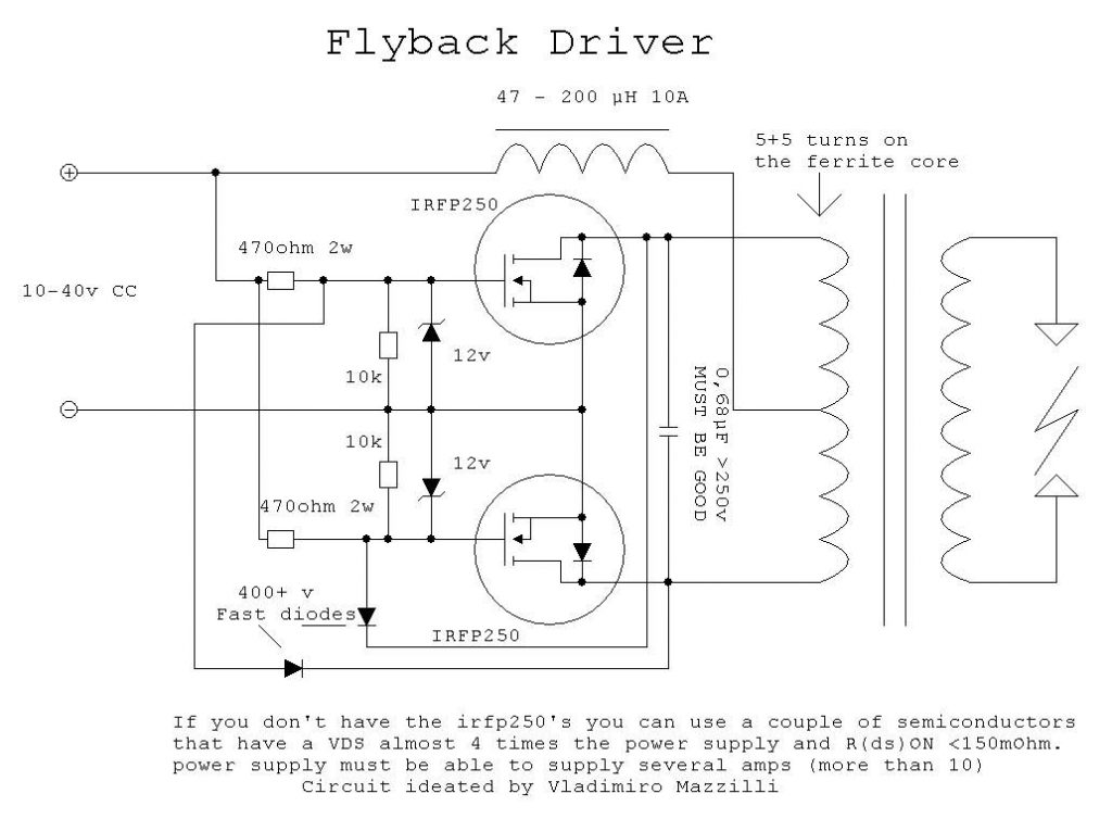
The ZVS driver, the HV flyback, capacitors and diodes used for the high voltage multiplier where bought from highvoltageshop.com
You can see a similar schematic of the ZVS sold by them:
The high voltage multiplier is made stacking 6 Cockcroft-Walton voltage doubler circuits.

Some more pictures of the multiplier and the X-Ray tube:
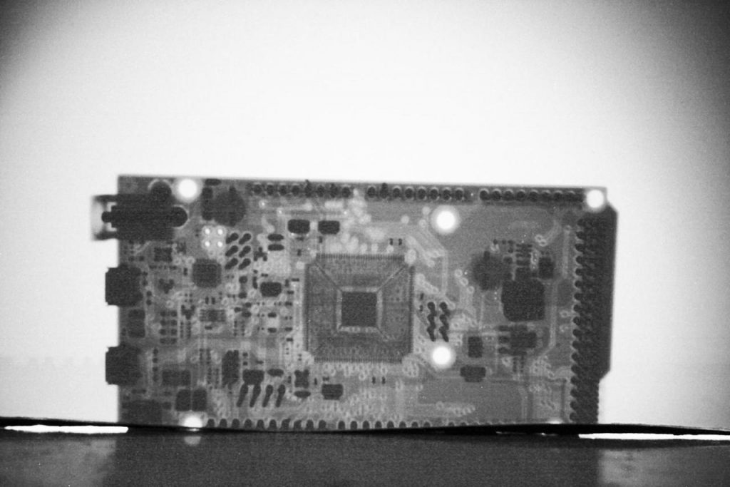
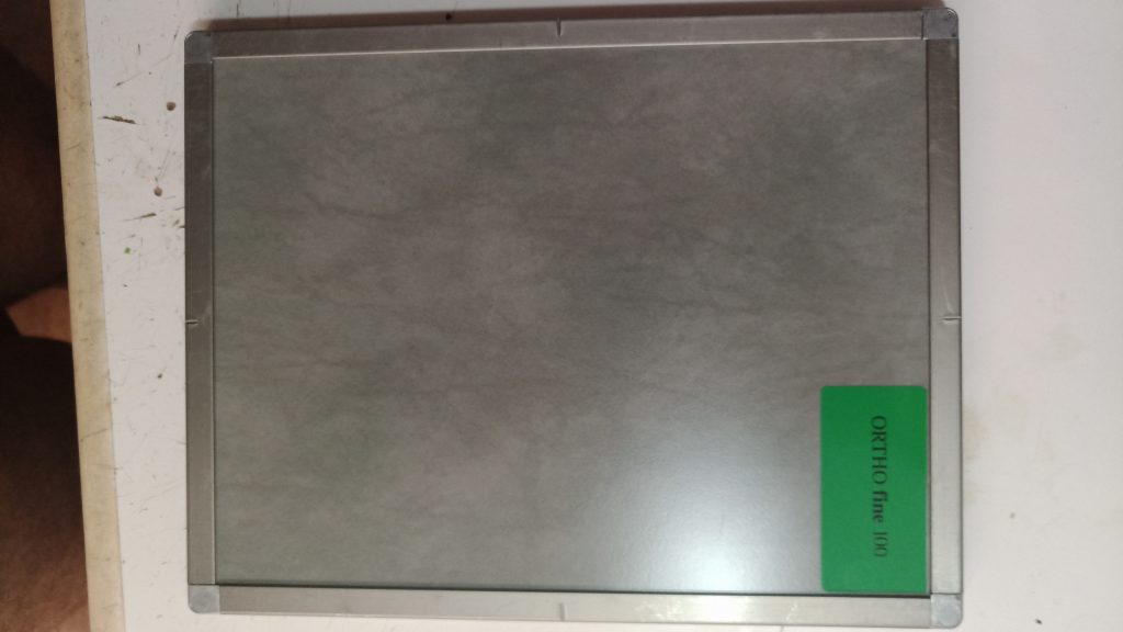
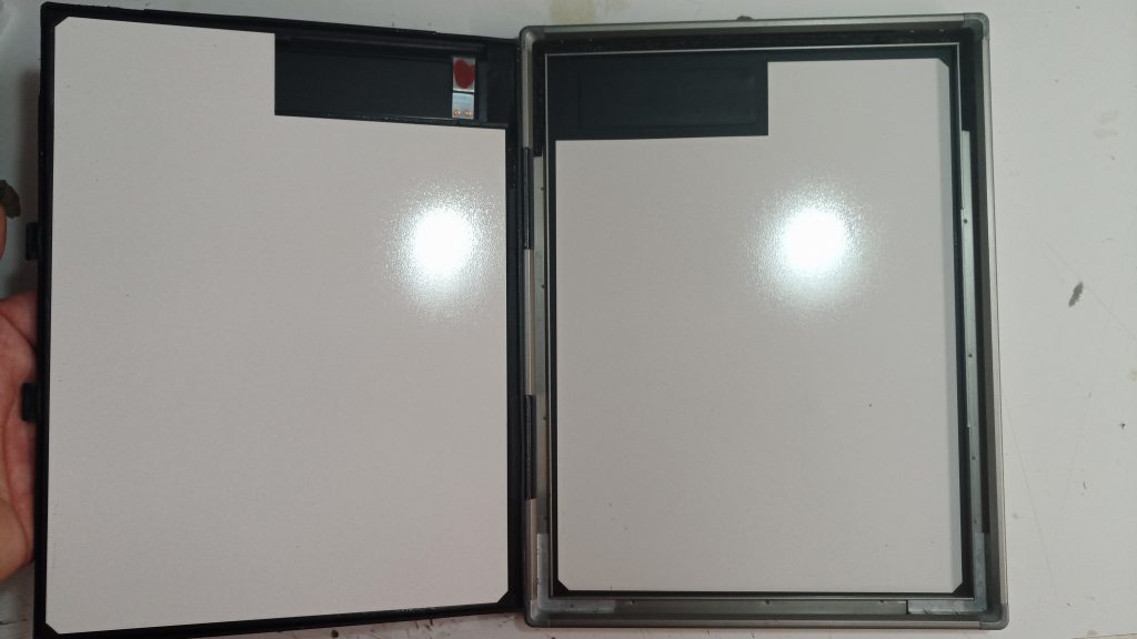
Using an X-Ray image intensifier screen positioned after the item to be inspected, you can take pictures of the shadows left where X-Rays cannot pass the object or are attenuated. Higher density appares as higher density shadows on the improvised “fluoroscopy” screen. You can get a proper X-Ray intensifier by scrapping an X-Ray medical cassette. Medical X-Ray casettes have glued on inner sides this kinds of screens. Them are sold on eBay with specified emission color and sensibility like blue or green fluorescence emission ORTHO 100 or 400.Look at the pictures below.
Carefully regulating high voltage and filament current, you can generate X-Rays into a broad range of energy so you can “trim” them to acomplish the needed job. For metallic objects you’ll need higher voltages, for insects you’ll need much lower voltages… you have to experiment. I stronly recomand the use of a CCTV circuit to see what appares into the fluoroscopy screen from a protected remote location like a different room. You can use a standard analog BW CCTV camera and a cheap LCD screen that accept AV input. It’s usually a yellow RCA female connector on the screen back or side. Use a remote control of the HV generator. You can leave filament turned ON but stay away protected by at least a concrete wall during operation.
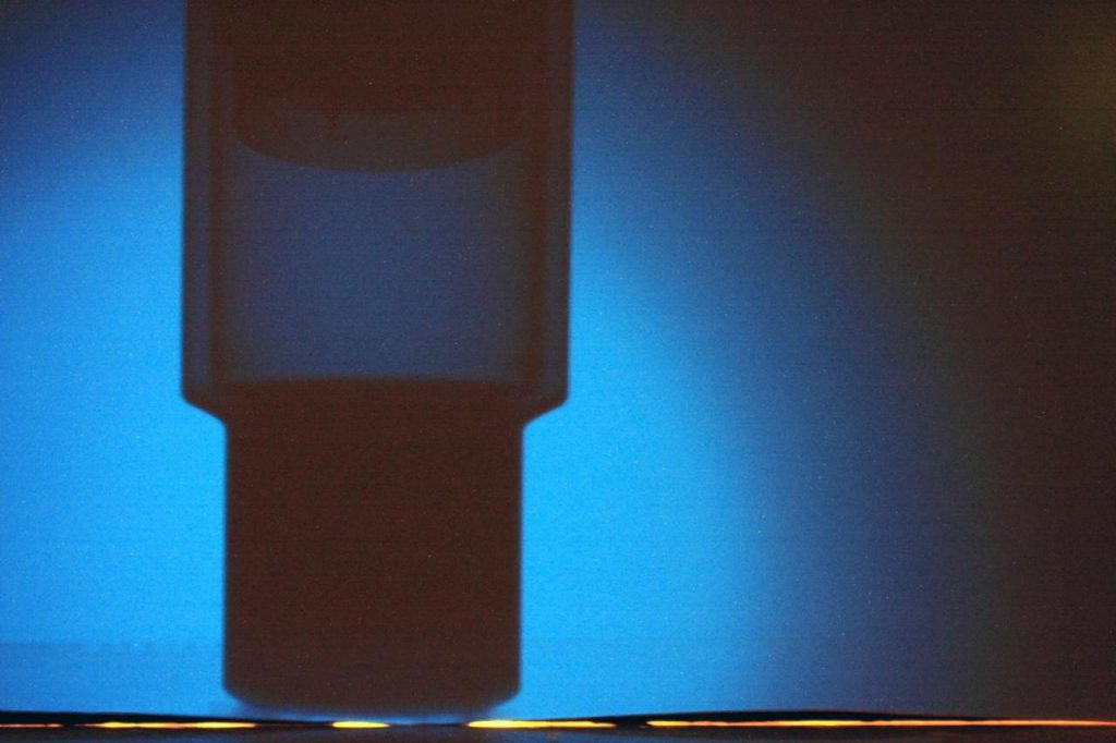
This is how looks an X-Ray intensifier screen that have blue characteristic. It’s a very fine grain screen. You can notice that the subject it’s a BDEG scintillation probe. The NaI(Tl) crystal on bottom it’s very dark because of it’s high density. The 1mm alluminium enclosure is clearly visible but it still permit to see the glass photomultiplier tube. Look how much free space there is between photo katode and first dynode! The glass body of the PMT is very evident. You can see also on the lower end of the image the yellow light emitted by the filament of the X-Ray tube. To protect the X-Ray intensifier for this light I’ve glued on it’s back a black cardboard pannel but… some light leaked!