INTRODUCTION
Over the last few weeks I’ve been experimenting with SiPMs to investigate:
- Optimal positioning of SiPMs along rectangular crystals
- Best readout circuit
- Bias power supply
- Optimal reflective layer and crystal surface preparation
CRYSTALS
The crystals I used were CdWO4 (5x7x30 mm) and CsI(Tl) (8x8x30 mm). I found them available in quantity at low cost. An additional advantage is that neither of them are hygroscopic.
SiPM
I tested the following devices:
- MicroFJ-30035 (3×3 mm) for positioning tests
- MicroFC-60035 (6×6 mm) for all other tests
REFLECTIVE LAYER AND PREPARATION
The CdWO4 material I had was already prepared for assembly, so let’s focus on CsI(Tl).
DISCLAIMER:
This process produces dust. Always wear gloves and a breathing mask. CsI(Tl) contains toxic thallium dopant—avoid contaminating yourself or the environment.
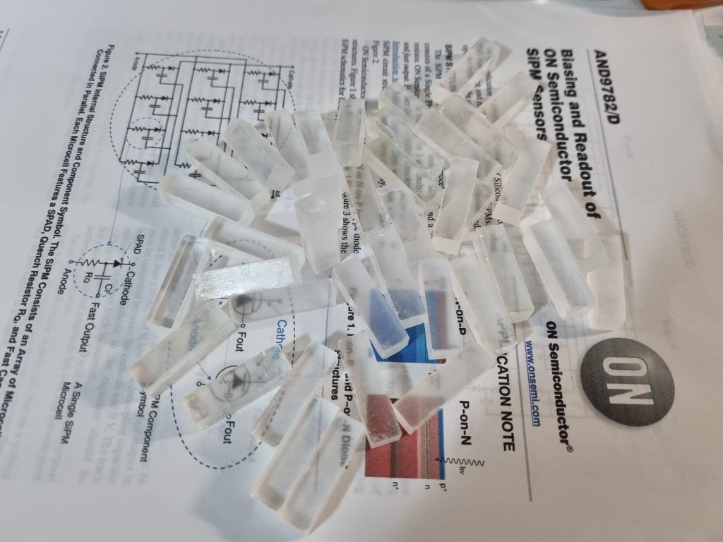
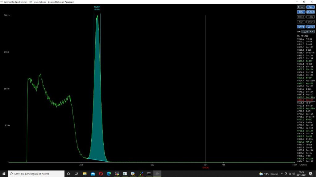
I purchased an 8x8x30 mm batch of CsI(Tl) scintillators some time ago. They came with rough surfaces and imperfections; first tests gave results between 6.4% and 10%. Such a wide range! To achieve consistency, they needed proper preparation, polishing, and assembly.
The first step is sanding all surfaces with ~800 grit sandpaper.
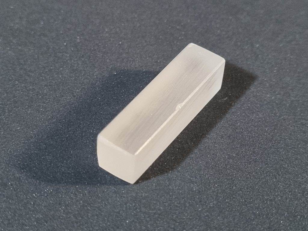
I also smoothed the edges a bit. The next step was cleaning with isopropyl alcohol applied on a soft tissue.
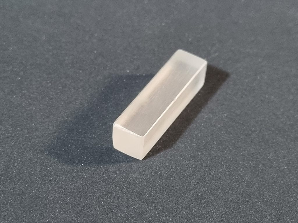
Now the crystal looks much clearer. It’s time to couple it to the SiPM and add a reflective layer.
SiPM POSITIONING AND OPTICAL COUPLING
I tested different SiPM positions along the crystal. Each location gave different results, but the best performance was obtained when the SiPM was placed at one end.
How to couple the SiPM to the crystal? Options include a drop of silicone optical grease, transparent grease, or—in my case—a special optical double-sided adhesive tape.
First, I applied the optical adhesive tape.
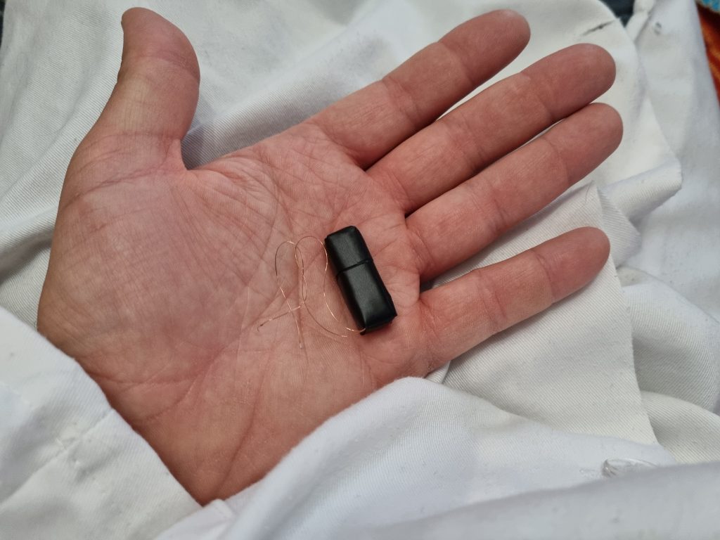
The SiPM was then fixed in place. Before this step I had already soldered two small enamelled copper wires directly to the device.
The crystal is wrapped with PTFE tape—standard unsintered 0.2 mm hydraulic tape, applied in five tightly wound layers. My tests with other reflective materials (titanium white paint, acrylic white paint) showed PTFE tape provides the best results.
Finally, the detector is completed—but only after covering it with aluminium or black tape to block ambient light.
READOUT CIRCUIT
For pulse extraction from the SiPM, I found that a transimpedance amplifier (TIA) is the best choice overall. It offers good noise immunity and wide bandwidth.
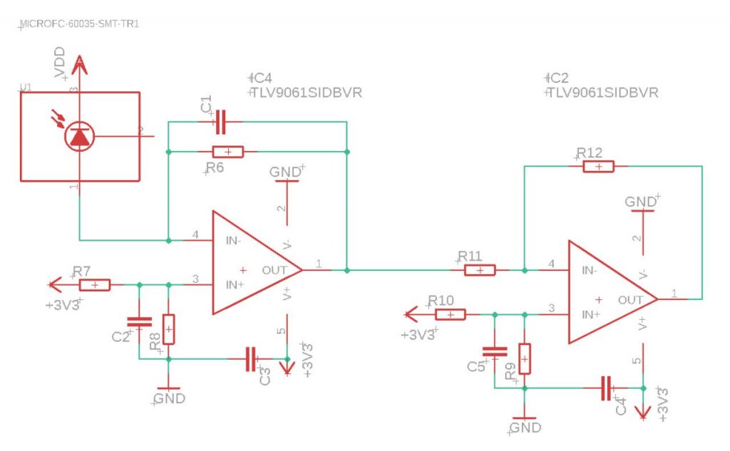
IC4 implements the TIA, with gain set by R6. The optimal value is between 470 Ω and 10 kΩ; I use 3.3 kΩ. Capacitor C1 compensates the SiPM capacitance to prevent oscillations. Its value must be determined experimentally—470 pF worked excellently in my case.
IC4’s bandwidth must be at least 10× the input signal’s bandwidth: typically ~10 MHz for CsI(Tl) and CdWO4, and 30–50 MHz for NaI(Tl). Faster op-amps can also be used.
Note: the R6/C1 time constant affects the pulse shape!
R7–R8 and R9–R10 form offset dividers for the op-amp. I used 10 kΩ resistors for each pair, allowing the output signal to swing positive or negative around ½ VCC.
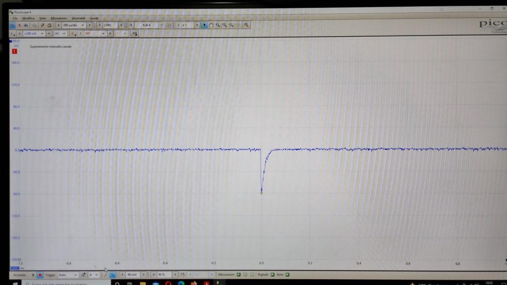
The output pulse shape is exactly as expected: a fast rising edge followed by an exponential decay. The second op-amp, configured as an inverting amplifier and buffer, produces positive pulses for the next stage.
The signal at this point can be sent to a shaping amplifier and then to an ADC + MCA for gamma spectroscopy. The crystal shown in this post improved from its original 10% resolution to ~8% after preparation.