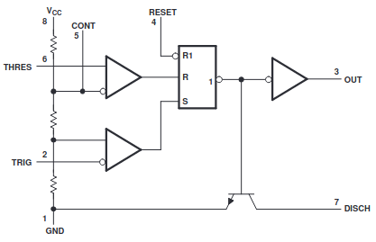
To better understand the internal operation and practical applications of the NE555 timer, I decided to rebuild it using discrete components. Although the datasheet provides a block diagram of its internals, it lacks detailed explanations—so I relied on trial and error to figure everything out.
Since my high-school days I’ve been using NI Multisim as my go-to electronics simulator. It’s perfect for quick “what-if” experiments without wasting real components or time.
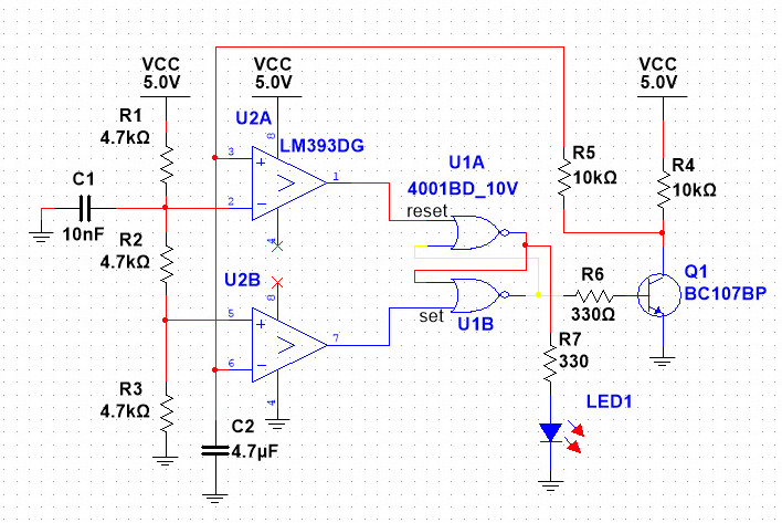
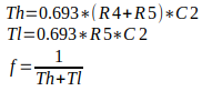
In the schematic above, I implemented an astable oscillator whose time constant τ is determined by R4, R5, and C2:
The NE555 takes its name from the three internal 5 kΩ resistors. In my discrete build they’re represented by R1, R2, and R3—chosen as standard 4.7 kΩ parts. These form a voltage divider that sets reference levels at one-third and two-thirds of VCC for the dual comparators. Capacitor C1 decouples the two-thirds node, though you could replace it with another circuit to shift the divider ratio for special functions.
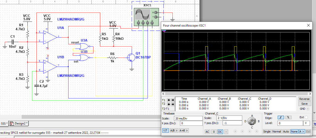
The simulation confirms that the discrete circuit behaves exactly like a real NE555. I cleaned up the schematic and exported it as a PDF, which you can download here: ne555_discrete.pdf.