partial FAIL
INTRODUCTION
During the latest pre-holiday days, I attempted to build a usable XRF (X-Ray Fluorescence) system. This material analysis technique employs an X-Ray source to excite a metallic alloy to be tested, causing its atoms to emit X-Rays, thus becoming “fluorescent.” Each metal emits X-Rays at different energy levels. With an appropriate detector, these energies can be detected and categorized to create an X-Ray spectrum, somewhat similar to what we do in Gamma-Ray spectroscopy, to identify the different elements in the alloy.
XRF could be used to identify the Gold percentage in an unknown or untrusted jewelry object.
THE PROBE
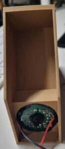
I decided to use an FEU-85 photomultiplier because I had one with its proper voltage divider base in stock. I also used a 2mm thick, 20mm diameter CsI(Tl) crystal as the scintillation detector for X-Rays. The crystal was simply optically coupled to the PMT entrance window with some optical grease, and two layers of 0.5mm thick PTFE were added as a reflector. The X-Ray entrance window was made out of black cardboard, and the probe was assembled with the help of black heatshrink tubing to shield the PMT/Crystal from light ingress. Five layers of 0.05mm thick mu-metal sheet were wrapped around the PMT body before sealing everything in heatshrink as an electromagnetic shield.
ELECTRONICS
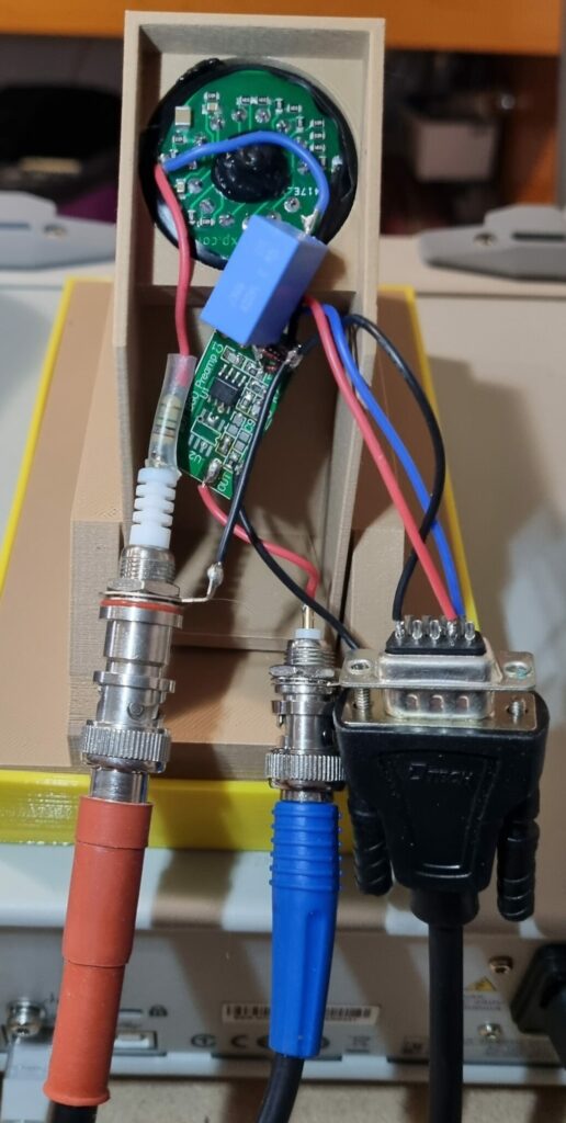
The output pulses from the PMT at these very low levels of X-Ray energy are very weak. I can only get 20mV peaks at 59keV! This necessitated the addition of a preamplifier circuit which amplifies the incoming pulses by a gain of 11 and adapts the 100Mohm PMT impedance to the 93ohm impedance of my spectroscopy system.
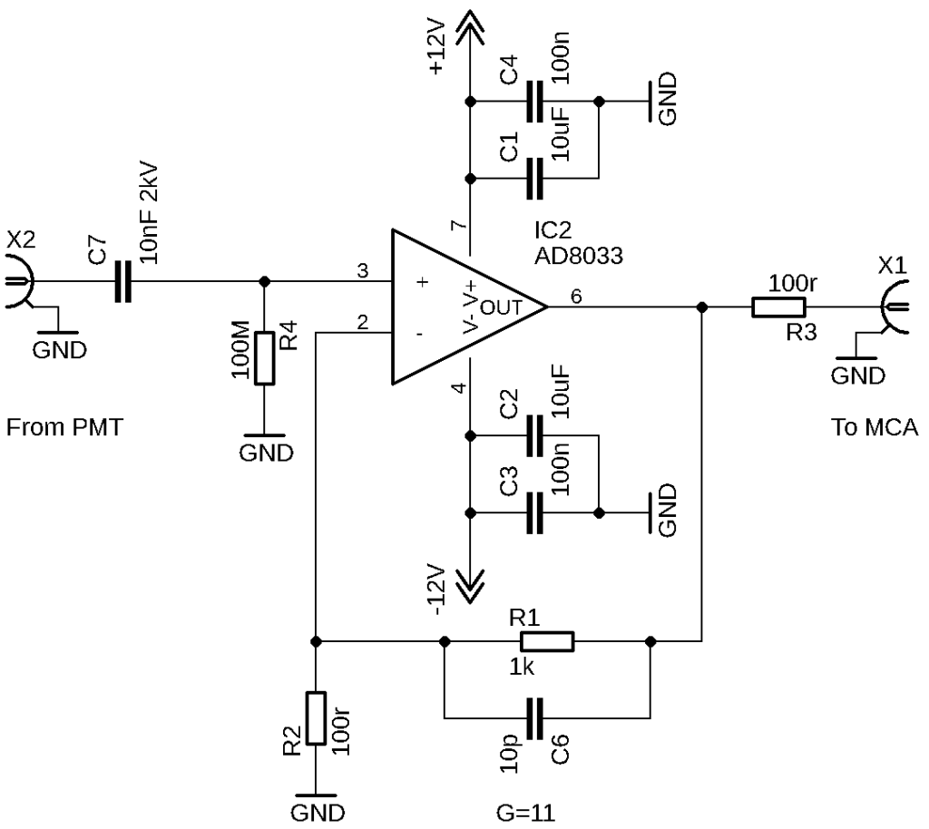
The schematic doesn’t show the PMT connection, but it’s straightforward: the PMT operates with +HV, and pulses are extracted with a 10nF 1600V capacitor from a 1Mohm load in series between the +HV SHV connector and the PMT Anode. It’s quite trivial, after all.
MCA
I used my standard NIM system with a shaping amplifier set to Tau 3uSec for CsI(Tl) material, and an ADC+556AIM interface board which communicates with EPICS. I use EPICS along with my AmericiuMCA application for spectrum visualization.
THE PROTOTYPE
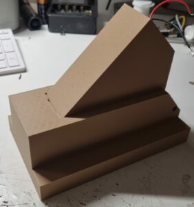
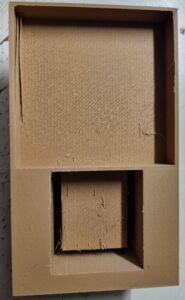
I used my 3D printer to manufacture a two-piece assembly: the base for rest/calibration of the detector head and the sliding detector/source assembly.
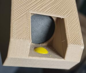
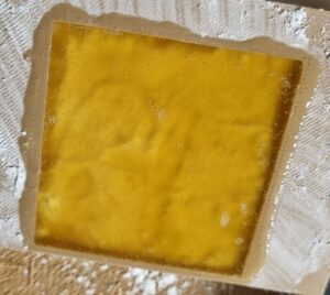
The detector/source assembly is simply a harness that carries the X-Ray scintillation probe and a 0.8uCi Am241 source (under the yellow blob) used as the excitation source. The probe and the source are positioned at a 90° angle.
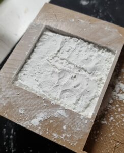
The base, where the detector/source assembly slides in to be stored, has an X-Ray shield that actually works also as crude calibrator. I made it by pressing a 10mm to 20mm thick wall of Barium Carbonate, which uses barium atoms as a shield and has strong 32keV detectable X-Ray fluorescence.
SHIELD TEST
The Barium Carbonate shield was sealed in place with a layer of polyurethane resin. Tests conducted both with and without it demonstrate its effectiveness.
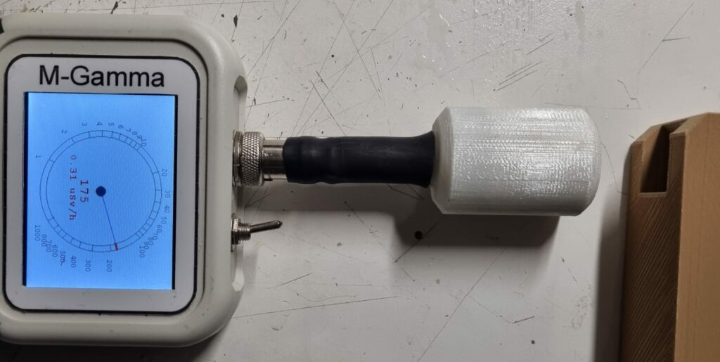
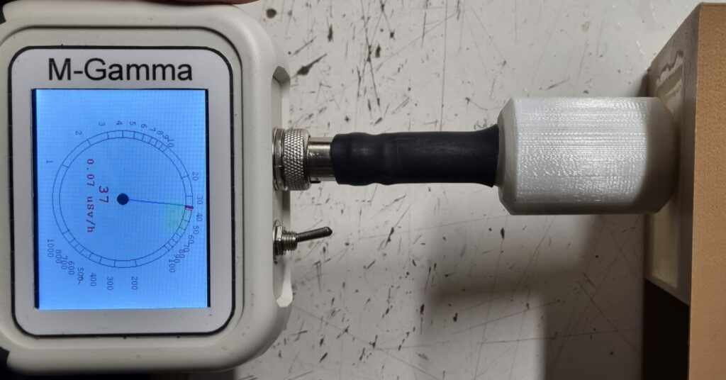
I can see the Barium XRay fluorescence on tests with detector slided-in its position over the base.
FIRST SERIES OF RESULTS
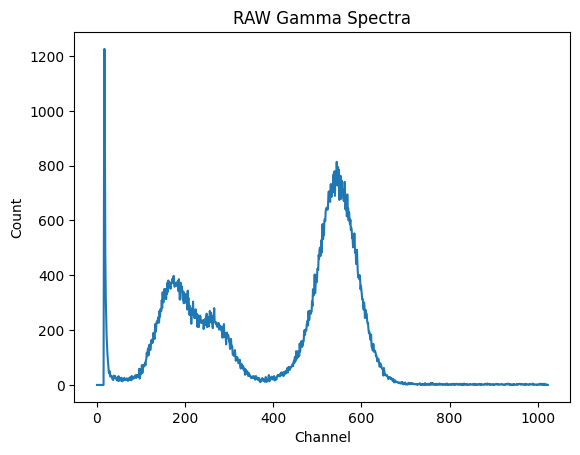
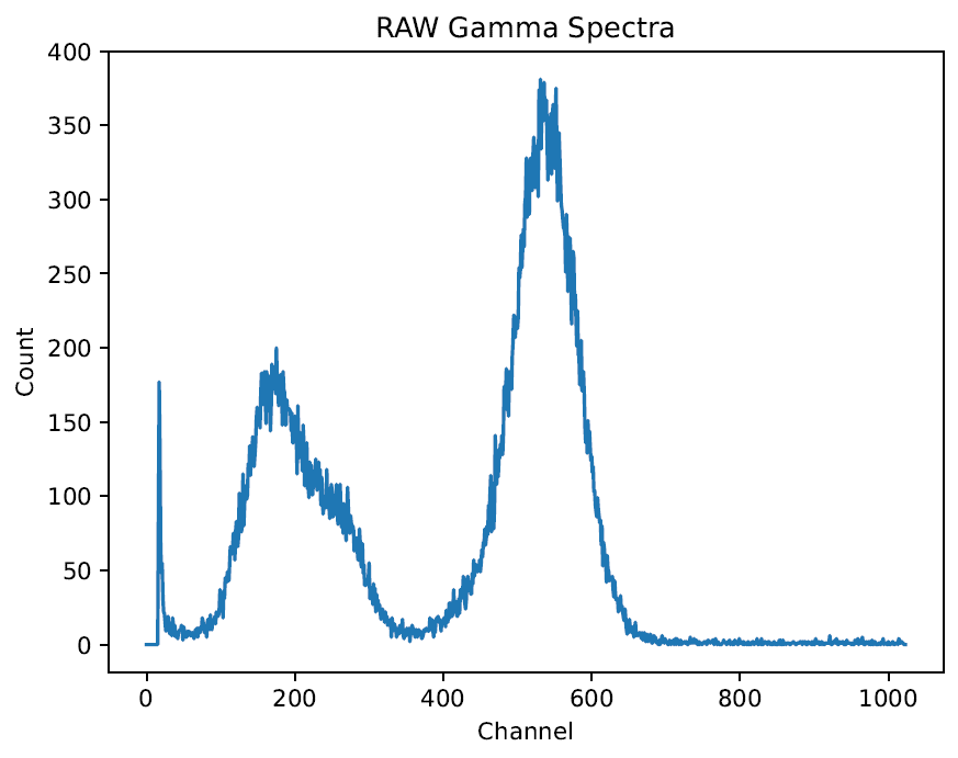
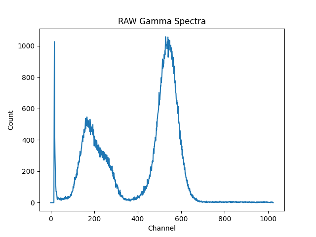
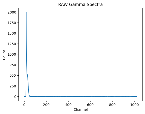
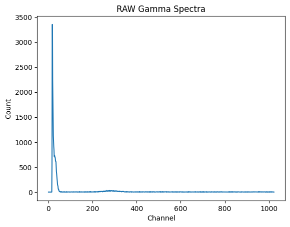
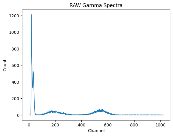
I conducted various tests. Under each chart you’ll find the description of the test. What I’ve learned? That I had to move the Am241 from its 90° position near the detector to another one to be found empirically cause the source interferes with the measures. I’ve also learned that I have to rise LLD a bit to cancel the electrical noise of my system on lowest energy channels.
SECOND SERIES OF RESULTS
After that I’ve moved the Am241 source away and rised the LLD of my system, I’ve done a second series of tests.
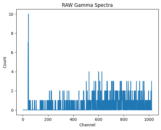
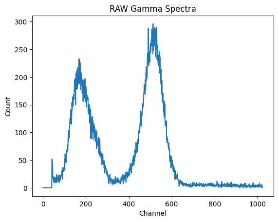
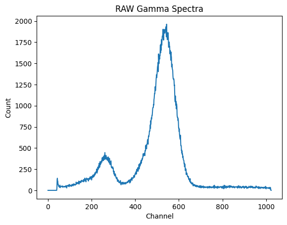
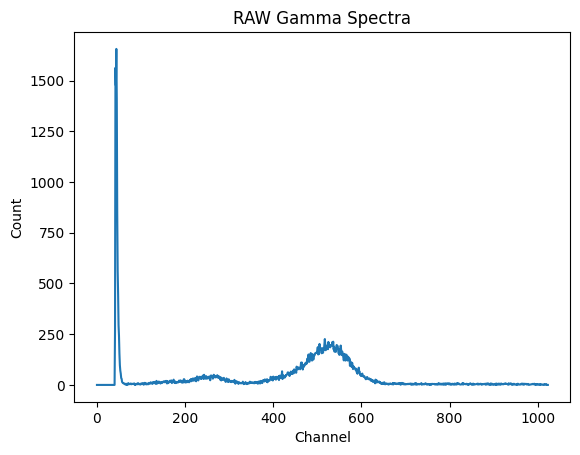
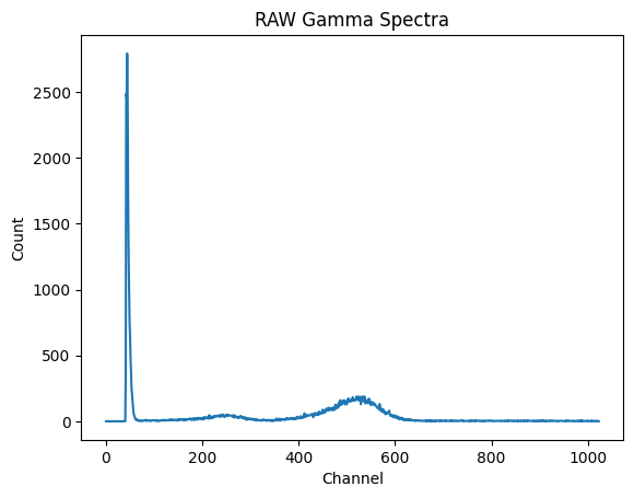
In conclusion, this system is rather useless for me. The probe itself anyway proved to be an effective scintillation probe for detection of Am241 and other low energy XRay and beta too.
Experiments to improve it will continue.