My First Didactic 8-bit Z80-based Computer
I’ve been fascinated with building a working computer from TTL chips since high school. To explore PC architecture and learn assembly language, I chose the Z80 microprocessor—introduced by Zilog in 1976—as my platform. As an enhanced Intel 8080, it became one of the most successful 8-bit CPUs, powering classics like the Sinclair ZX Spectrum, Radio Shack TRS-80, and countless early CP/M machines.
Project Overview
I kicked off this project by following Grant Searle’s elegant minimalist design: Grant’s 7-chip Z80 Computer. Remarkably, this schematic delivers a fully functional computer with just seven ICs.

UART Modifications
The original UART/RS232 converter wiring gave me headaches: despite double-checking every connection in Grant’s schematic, no data came through the serial port. I eventually simplified the setup by removing all RTS handshaking and using a direct RX-TX converter between the Motorola 6850 ACIA and the DB9 connector:
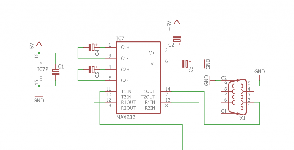
No jumpers between DB9 pins, no RTS complications—just a straightforward link. The 6850 ACIA is a robust serial interface, but it demands careful timing, as you’ll see below.
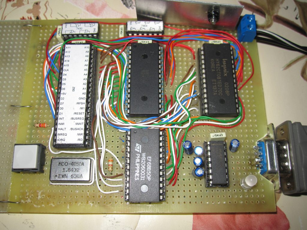
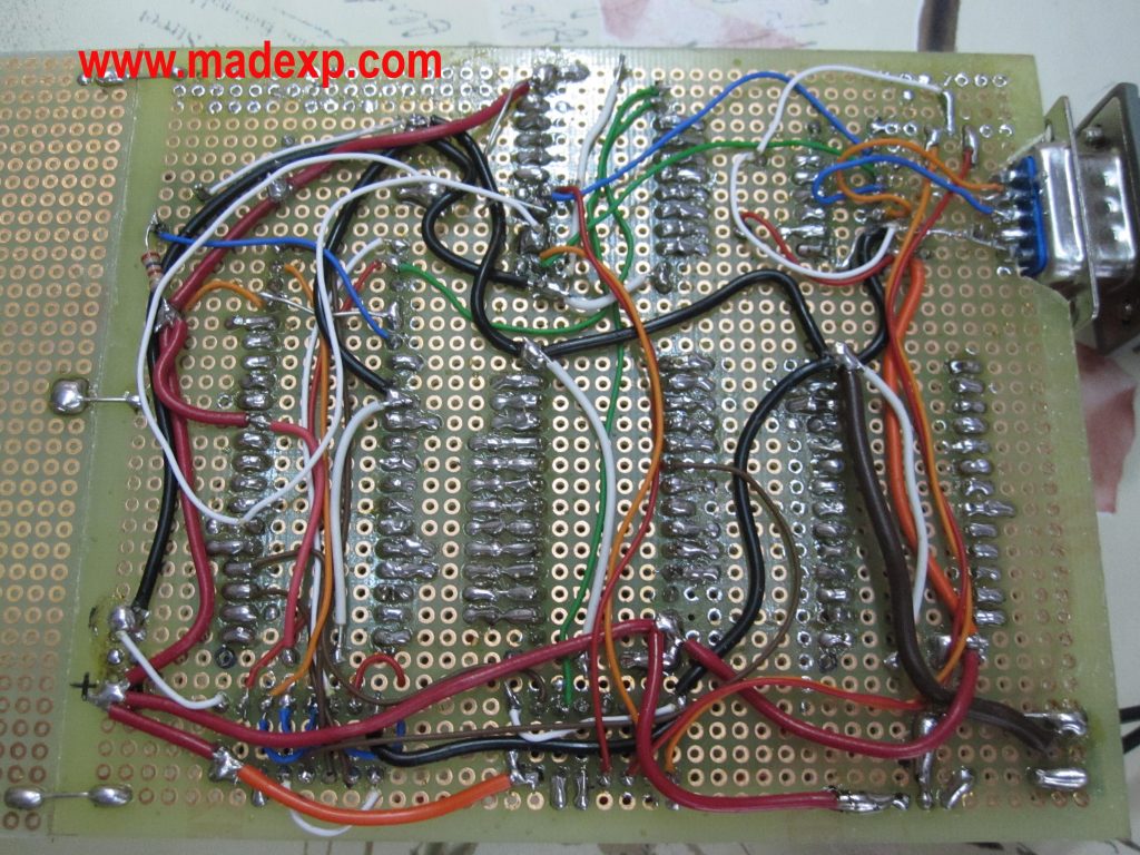
Construction Details
I assembled the entire system with point-to-point wiring on a veroboard. Though more laborious than a PCB, this method offers unrivaled flexibility for tweaks and debugging. Communication is handled over RS232, an old but rock-solid protocol.
Clock and Timing Considerations
My schematic mostly follows Searle—except for the clock source and the init.asm code that drives the 68B50 ACIA. The Z80 happily runs from DC up to its rated max (2.5–8 MHz in original variants). I started with a single 1.8432 MHz crystal for both CPU and ACIA, then switched to a split-clock arrangement: a 10.240 MHz crystal for the CPU, and the original 1.8432 MHz just for the ACIA. With a divider of 16, this setup yields a clean 115200 bps serial link.
ACIA Configuration Details
Since I’m not using RTS, I had to adjust the RTS_HIGH and RTS_LOW values in init32.asm. The control register (CR) bits for the MC6850 are set as follows (from MSB to LSB):
1 - CR7: Interrupt enabled
1 - CR6: part of RTS HIGH selection
0 - CR5: part of RTS HIGH selection
1 - CR4: 8 data bits
0 - CR3: +1 stop bit
1 - CR2:
1 - CR1: Clock divisor bit 1
0 - CR0: Clock divisor bit 0 (divider = /64)
To achieve 115200 bps with a 1.8432 MHz clock, you need a divider of 16 (1.8432 MHz / 115200 bps = 16). That means CR1=0, CR0=1. The final values become RTS_HIGH = 0xD5 (110101012) and RTS_LOW = 0x95.
Solving the MC6850 Timing Challenge
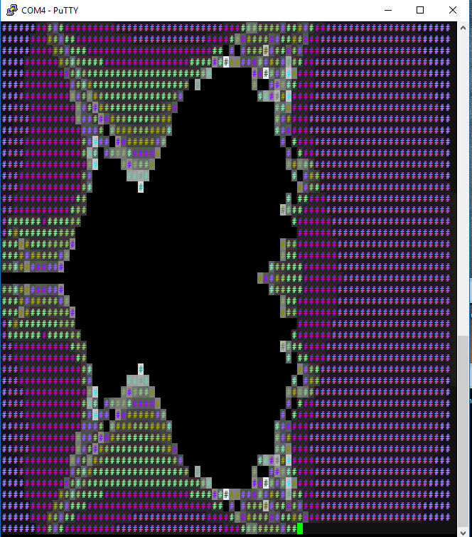
The MC6850 was originally tuned for the MC68000’s slower timing, so at higher Z80 clocks it sometimes won’t reset correctly. My quick “hot-swap” fix—removing and reinserting the ACIA under power—worked, but wasn’t elegant. Thanks to Joe Helmick’s advice, a simple 1 kΩ pull-up on the /INT line now reliably solves the boot issue. Joe also shared his own Z80 homebrew, complete with a Conway’s Game of Life demo: Conway’s Game of Life on Z80.
Performance Testing
To benchmark the CPU, I ran the classic Mandelbrot fractal generator from the RC2014 project. This test stresses the Z80’s math and memory access:
Results:
- 1.832 MHz clock: 46 m 52 s
- 10.240 MHz clock: 8 m 31 s
Nearly linear speedup, reflecting the Z80’s fixed-cycle instruction timing.
Programming Resources
Interested in programming? Check out these manuals:
Future Enhancements
Some ideas for next steps:
- Add a parallel I/O port for custom peripherals
- Implement bank-switched memory
- Port CP/M to the system
- Interface period-correct storage devices (e.g., tape, floppy)