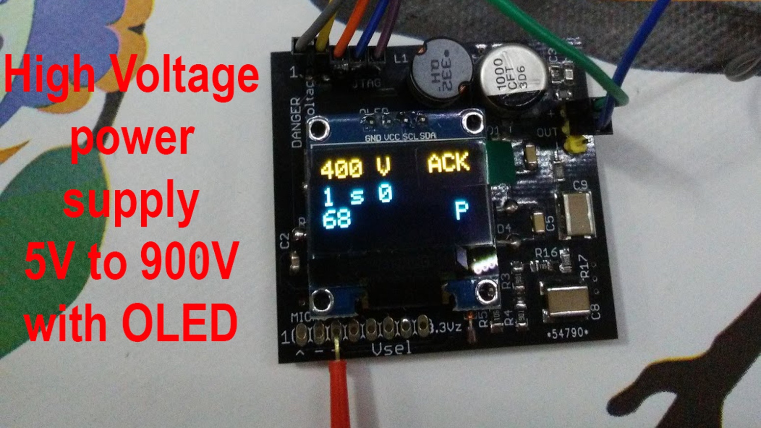
This project response to my need of an universal high voltage power supply to be used with mostly all type of geiger tubes that I have in my collection.
I’ve needed a selectable output voltage between 300V and 900-1000V, low power output, on board pulse counter and maybe a display. All powered by 5V
THE PROJECT
I’ve started the design of this voltage converter scrapping my “Madexp PMT adapter” power supply section. For more info visit www.madexp.it
In that old project I’ve generated 900-1600V out with a single 5V source from USB via a simple TTL variable duty cycle oscillator.
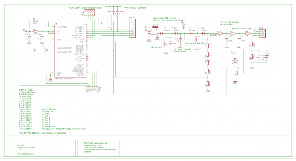
I’ve replaced that oscillator with an Atmega328P MCU so I was capable to add programmable voltage output via 4 bit parallel interface, pulse counting and if I need, an 0.96″ OLED display.
Into this schematic there is a missing 100pF capacitor from pin INT0 to ground. The oled display have also two 1K pull up resistors on I2C lines
On the first prototype I’ve easily reached 1650V of output but into the second (current) production prototype I could not exced 900V because of the insufficent spacing between HV multiplier and the MCU. This is not an issue because mostly all geiger tubes works with less than 900V.
The board is thinked to be used as a module of a bigger project or stand alone.
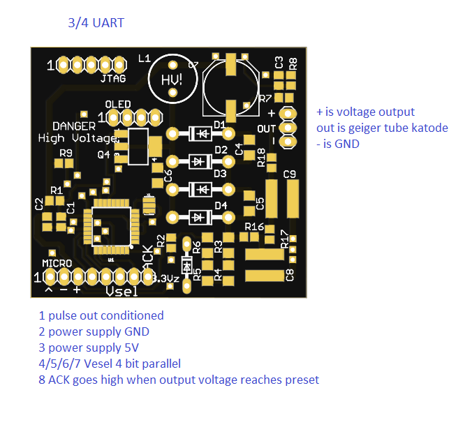
As module of a bigger project, you can simply omit the OLED display and connect the 8 pin connetor to your project. The 4 bit parallel interface selects voltage output and the ACK pin goes HIGH when the output voltage selected is reached/stabilized.
If you wish to use the module as stand alone, you can connect the OLED and a geiger on the + and OUT pins, 5V supply from a battery (voltage regulator NOT included) and you can see the voltage, pulses per minute (CPM) and last minute reading on the display. The output voltage is selected by make a soldering bridge on voltage selection jumpers. It permit you to made a pocket size geiger counter with very low effort.
If you wish to made a geiger clicker without display you cold simply connect a little speaker between pin 1 of the 8 pin connector marked as “^” and GND, omit OLED.
The 3 pin output connector have a geiger katode connection marked as “OUT” and also permit you to exclude the pulse counting and conditioning section connecting the powered item directly between HV and GND.
There is also a JTAG connector for uploading new firmware via a USBAsp programmer. During operation the jtag pins 3 and 4 becomes RX/TX uart. Pin 1 is GND.
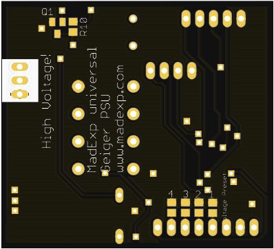
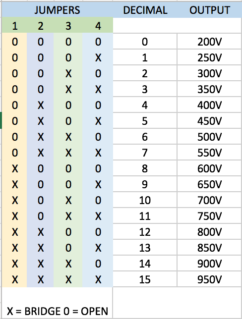
The voltage selection jumpers are made to select output voltage when the board is used stand-alone. Make a solder bridge according with the table below and you’ll get the corresponding output voltage out.
SOFTWARE
The firmware is in currently developement but it’s already stable, counts pulses, display voltage and also send info like pulses/voltage via UART. You can download it from here: firmware_0.1
KICKSTARTER
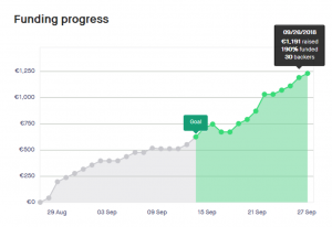
This project was published on Kickstarter and was active for pledges during all the month of September. I’ve realy appreciated the 30 pledges (one was for two boards) received, that made me capable of buy all the tooling needed to build the boards and further inprove their design.
At the moment the boards are travelling around the globe to reach their owners. I’ve send most of them to USA and Australia but also to Japan, Germany, Switzerland, Canada, Spain, Russia, Ireland and UK. I’m very happy about this result. This make me feel like a multi national corporate, it stimulate my hungry for new projects. Thank you again and stay tuned, you’ll see some new crazy project soon!
MANUAL
Here you cand download the board manual complete with schematic MadexpHV manual 0.3